|
Note: The MKC-1 is undergoing a redesign and will be out of stock
for
the time being. Please check back here for any updates.
Introduction
The MKC-1 provides a means to add limited MIDI control to older
synthesizers by interrupting the electrical path between the keyboard
switch assembly and the synthesizer control board.
MIDI note-on and note-off messages that are received will play corresponding
notes on the synthesizer.
Keys pressed on the synthesizer keyboard will produce MIDI note-on and
note-off MIDI output.
If the local control option is enabled, the synthesizer will also play notes normally.
If local control is turned off, the synth keyboard will only produce MIDI output, but will not play
notes on the synthesizer. Local control can be enabled or disabled with a MIDI command, or by a
jumper (or wired toggle switch) on the MKC-1 circuit board.
A jumper option also can be used to enable or disable MIDI OMNI mode. With OMNI mode on, the MKC-1
will respond to note and control messages on all 16 MIDI channels. When OMNI mode is off, the MKC-1
will only respond to messages on the MIDI channel selected by the DIP switch.
The MKC-1 is specifically designed to work
with connectors and keyboard matrix layouts used by Oberheim synthesizers.
It will work with the OB-SX, OB-X, OB-Xa and OB-8. The MKC-1 operates over
a range of 64 MIDI notes starting with MIDI note 36 and is not velocity
sensitive.
For use with the Sequential Circuits Prophet 5 synthesizer, a special inverter board is used to
produce the correct logic and wiring arrangement.
Scroll down for ordering information
Installation
Turn off the synthesizer power before starting the installation.
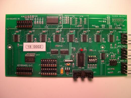
The MKC-1 has 16-pin IC sockets that are used to connect ribbon cables to
the synthesizer. The ribbon cables have a stripe along one edge that
indicates the cable orientation. The stripe should always go on the side
of the socket with the notch in the end.
The sockets labeled, KEYBOARD IN and KEYBOARD OUT intercept
the
synthesizer keyboard signals. The original synthesizer keyboard cable
should be unplugged from the synthesizer main circuit board and plugged
into the MKC-1 KEYBOARD IN socket. A new ribbon cable (supplied
with
the MKC-1) connects from KEYBOARD OUT to the keyboard socket on the
synthesizer main board.
Power for the MKC-1 is taken from any convenient 16-pin digital IC on the
synthesizer board. This usually turns out to be a 74C42 or 74LS42 located
somewhere near the keyboard socket. Remove this 74C42 IC and re-install
it on the MKC-1 board in the socket labeled, J1. Connect the
second
ribbon cable supplied with the MKC-1 from socket J2 to the now
vacant
socket on the synthesizer board. Be sure to orient the IC and cables
correctly.
Two MIDI jacks are supplied with the MKC-1 and can be mounted in any
convenient location. The MIDI jack cables connect to the MKC-1 with Molex
connectors that are keyed for correct orientation. The MIDI IN jack
should connect to the MIDI IN Molex connector on the MKC-1. The
MIDI
OUT jack can be connected either to the MIDI OUT connector, or the
MIDI
THRU connector if you don.t intend to use the synthesizer keyboard to
produce MIDI out.
The MKC-1 board can be mounted in any convenient location using the
standoffs supplied. When using the stick-on nylon standoffs, be sure that
the mounting surface is clean and dry before adhering them.
If everything is connected correctly, the LED on the MKC-1 should light up
when the synthesizer is turned on, and the synthesizer keyboard should
work normally.
Operation
A four-position DIP switch on the MKC-1 board sets the MIDI channel for
send and receive. The following chart shows the switch settings for the
available selections:
| SW4 | SW3 | SW2 | SW1 |
MIDI Channel |
| DOWN | DOWN | DOWN | UP |
1 |
| DOWN | DOWN | UP | DOWN |
2 |
| DOWN | DOWN | UP | UP |
3 |
| DOWN | UP | DOWN | DOWN |
4 |
| DOWN | UP | DOWN | UP |
5 |
| DOWN | UP | UP | DOWN |
6 |
| DOWN | UP | UP | UP |
7 |
| UP | DOWN | DOWN | DOWN |
8 |
| UP | DOWN | DOWN | UP |
9 |
| UP | DOWN | UP | DOWN |
10 |
| UP | DOWN | UP | UP |
11 |
| UP | UP | DOWN | DOWN |
12 |
| UP | UP | DOWN | UP |
13 |
| UP | UP | UP | DOWN |
14 |
| UP | UP | UP | UP |
15 |
| DOWN | DOWN | DOWN | DOWN |
16 |
The MKC-1 will normally receive data on all 16 MIDI channels (OMNI mode).
OMNI mode can be turned off with a MIDI control command, in which case the
MIDI receive channel will be determined by the switch setting (above).
The MKC-1 supports the following standard MIDI commands. All byte values
are shown in hexadecimal, with .x. representing (MIDI channel . 1) and
.XX. meaning .any value from 0 to 7F..
Local Control ON/OFF (received only)
	Bx 7A 00 = Set local control off
	Bx 7A 7F = Set local control on

OMNI mode ON/OFF (received only)
	Bx 7C 00 = Set omni mode on (receive on all MIDI channels)
	Bx 7D 00 = Set omni mode off (receive on channel set by switches)

All Notes Off (received only)
	Bx 7B XX = Turn off all notes

Note On/Note Off (transmitted and received)
	9x   = Note on
	8x   = Note off
(Note number range = 24 to 63.  Transmitted velocity = 40.)

Active Sensing
	FE = Active sensing (received only)
|