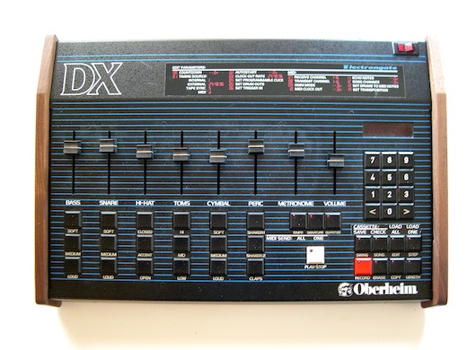
Oberheim DX MIDI Upgrade Installation
The Electrongate MIDI Upgrade Kit for the Oberheim DX drum machine adds MIDI capability and additional sync capability
to the DX or the Stretch DX. The kit version can be easily installed by anyone who can operate a screwdriver.
These instructions will take you through the process, step by step.
Parts supplied with the Basic Electrongate MIDI Kit:
- (1) Assembled and tested MIDI circuit board.
- (2) Replacement firmware EPROMs
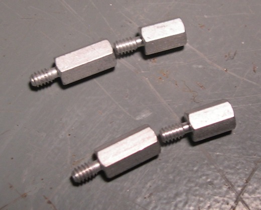
- (4) #6 threaded 1/2 inch and/or 3/8 inch standoffs.
- (1) MIDI cable assembly with jack mounting plate.
- (1) Addendum to owner's manual.
- (1) Installation instructions.
- (1) Front panel stickers
Optional accessories that may be ordered with the Basic Kit:
- Set of genuine walnut end panels to replace the original plastic parts
- Magnetic RAM option (assembled on the MIDI circuit board)
Tools required for installation:
- #2 Phillips screwdriver
- 1/4 inch nut driver
- Small flat-blade screwdriver or DIP IC chip puller

Installation: Step By Step
- Save your DX sequences to tape and verify them before beginning installation.
- Turn off the power and disconnect the AC power cable from the DX.
- Remove the two screws on the front of the DX and open the cover.
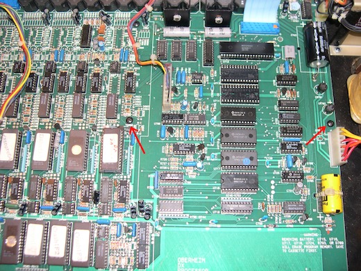
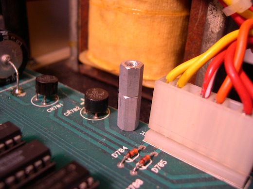
- Remove two screws from the DX main board as shown below and set them aside. These will
be reused later. Note: If your DX has the Sync-To-Tape modification installed, there will be a narrow
circuit board installed between these locations. Remove the screws from this circuit board but leave the
circuit board and standoffs that hold it up in place.
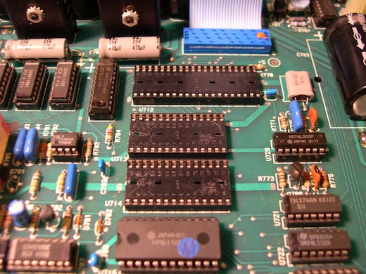
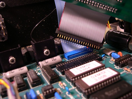
- Remove the two operating system EPROMs (U713, U714) from their sockets. Use a small screwdriver to lever the
ICs from the sockets, first lifting a little on one end, and then a little on the other end until they
can be removed. Set these EPROMs aside.
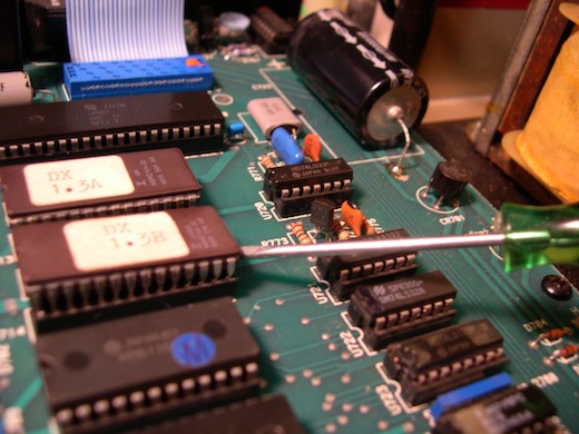
- Remove the Z80 processor (U712) from its socket and set it aside.
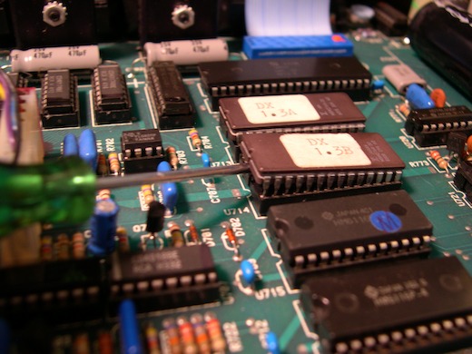
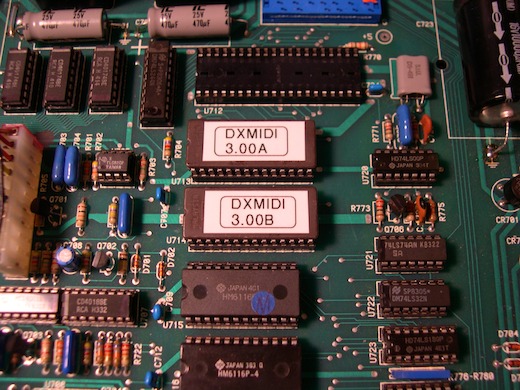
- Install the supplied DXMIDI EPROMs in place of the old ones. EPROM "A" goes in the
socket closer to the back of the machine, EPROM "B" goes in the other socket. Be sure
to line up the notches in the EPROMs with the notches in the IC sockets.
- If you have the Magnetic RAM version of the Electrongate DX MIDI upgrade, also remove the four
6116 RAM chips (U715, U716, U717 and U718) from their sockets.
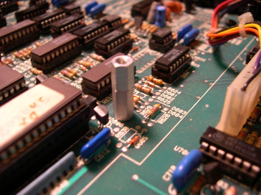
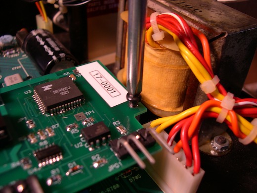
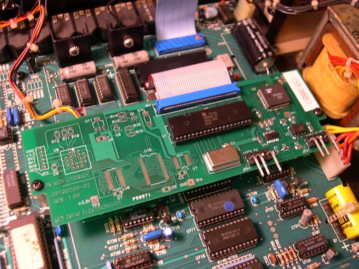
- Install the supplied standoffs in the holes where you removed the screws earlier and tighten them
until they are snug, but do not overtighten. Use one each of the 1/2 inch and the 3/8 inch standoffs
or two 1/2 inch standoffs in each position. If your DX has the Sync-To-Tape mod, just use one standoff
on each side, attaching them through the holes in the Sync-To-Tape board, into the
existing standoffs below.
- Plug the 40-pin ribbon cable connector into the Z80 socket on the DX main board. Be sure to
line up all the pins correctly and press down firmly to seat the connector in the socket.
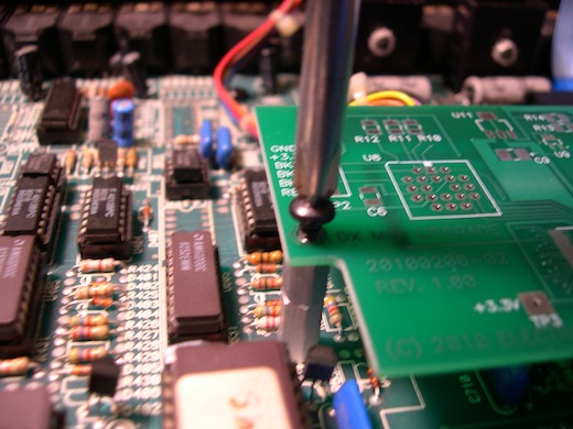
- Mount the MIDI board on the new standoffs using the screws removed earlier.
- If you ordered the walnut end panel option, take off the old end panels by removing two
screws from each panel. Replace the old panels with the new ones, placing the panel with the
MIDI jacks on the right side of the machine.
- If you did not get the new end panel option, you can use these instructions as a guide to
cut
an opening in the right side end panel, or optionally drill holes and mount the MIDI jacks somewhere on the
rear panel of the DX.
- Connect the MIDI jack cables to the MIDI board. Connect the corresponding cables to MIDI In
and MIDI Out as indicated on the board.
- Reconnect the power and hold down the ERASE button the first time you power up the DX
after installing the upgrade. This will initialize the RAM. Verify that the DX is working
and then reload your sequences from tape.
- Make sure the surfaces are clean and dry, then affix the supplied stickers to the DX front
panel as shown. The large sticker showing the edit modes goes on the flat top of the front panel.
The "MIDI SEND: ONE ALL" sticker should be placed so that "ALL" is below the
TEMPO button and "ONE" is below the SIGNATURE button. The CASSETTE label is meant to cover the
old CASSETTE text, above the top row of four control buttons, as shown.
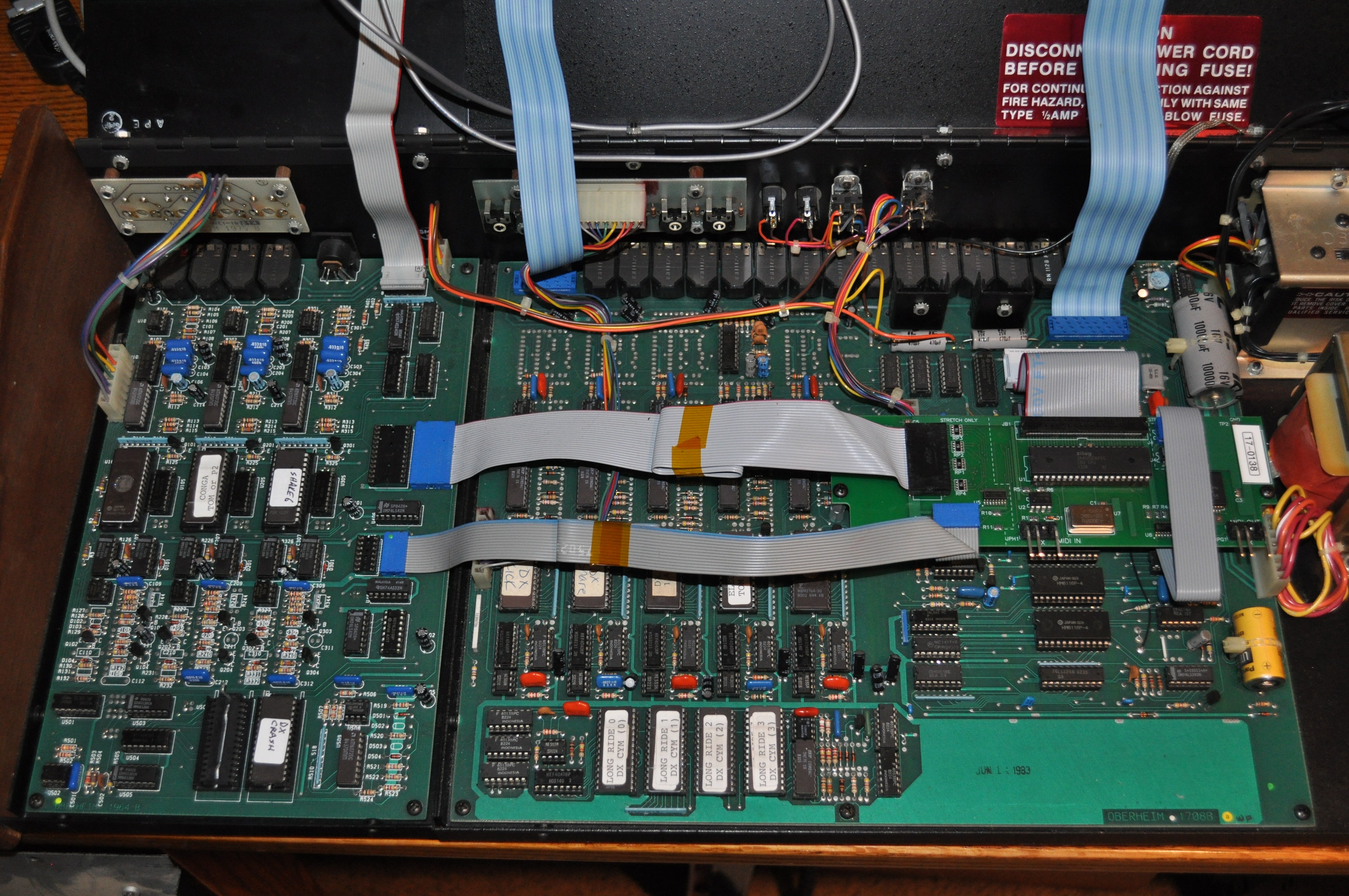
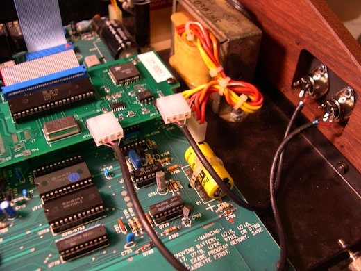
- Stretch Installation only
Unplug the two ribbon cables that connect the Stretch circuit board to the
main DX board, and connect them to the MIDI board as shown in the photo
below. You might want to fold and tape the cables to make them neat. Plug
the large cable into socket J5 and the small cable into socket J3.
Relocate the 6116 RAM IC (U405) from the Stretch board to the socket on
the main board where the large cable was just removed. Remove IC U407
(74LS32) from the Stretch board. Connect ribbon cable J4 to socket U722.
The cable will go up and over the front and then under the MIDI board.
The installation should look
like
this:
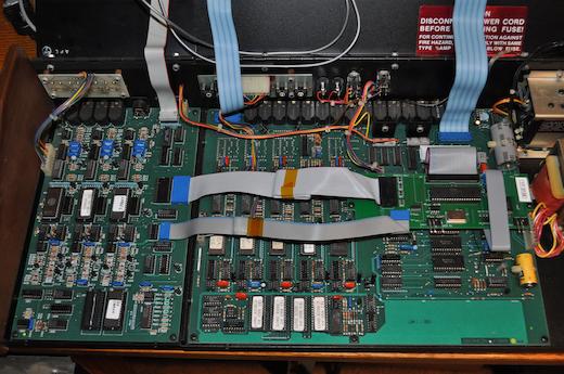
(Click to enlarge image)